Ceramic Capacitors Explained: Expert Insight into Ceramic Capacitor Tech Talk
Ceramic capacitors are fundamental components in modern electronics, powering everything from smartphones to industrial equipment. These tiny but mighty devices store electrical charge and filter signals with remarkable efficiency, making them indispensable in circuit design. Whether you’re building a custom PC, upgrading laptop components, or diving into embedded systems, understanding ceramic capacitor technology is essential for anyone serious about electronics.
In this comprehensive guide, we’ll explore the science behind ceramic capacitors, their diverse applications, performance characteristics, and why engineers worldwide depend on them for mission-critical circuits. From multilayer ceramic capacitors (MLCCs) to specialized high-voltage variants, we’ll examine what makes these components tick and how to select the right one for your project.
What Are Ceramic Capacitors?
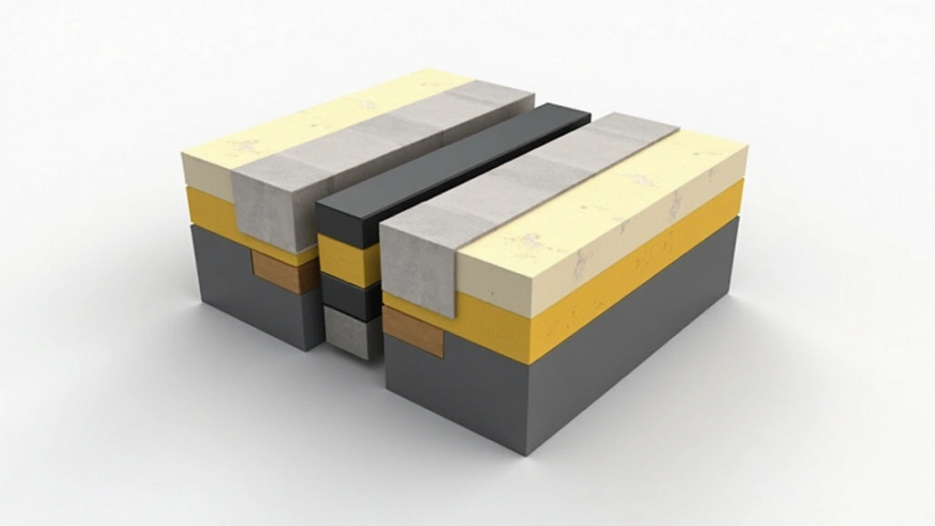
Ceramic capacitors are passive electronic components composed of two conductive plates separated by a ceramic dielectric material. The ceramic acts as an insulator that allows the capacitor to store electrical energy through the accumulation of charge on opposite sides. When voltage is applied across the plates, electrons accumulate on one plate while positive charges accumulate on the other, creating an electric field within the ceramic material.
The ceramic dielectric is the defining feature that distinguishes these capacitors from other types. Common ceramic materials include titanium dioxide, barium titanate, and various lead zirconate titanate (PZT) compounds. These materials possess exceptional dielectric properties, allowing them to store significant charge in a compact form factor. Ceramic capacitors have become the industry standard for consumer electronics because they offer excellent performance-to-cost ratios and remarkable reliability.
Multilayer ceramic capacitors (MLCCs) represent the most common variant found in modern devices. These components layer dozens or even hundreds of thin ceramic sheets with alternating metal electrodes, dramatically increasing capacitance density. A single 0402-sized MLCC can provide capacitance values that would require significantly larger components using older technology.
How Ceramic Capacitors Work: The Physics Behind the Technology
Understanding ceramic capacitor operation requires examining the fundamental physics of dielectric materials. When an electric field is applied across a ceramic dielectric, the material’s atomic structure responds by polarizing—the electron clouds shift relative to their nuclei, creating induced dipoles. This polarization phenomenon is what enables the ceramic to store electrical energy efficiently.
The capacitance value depends on three primary factors: the area of the conductive plates (A), the distance between them (d), and the dielectric constant (κ) of the ceramic material. This relationship is expressed through the capacitance formula: C = κε₀A/d. By optimizing these parameters—particularly through multilayering—manufacturers can achieve impressive capacitance values in remarkably small packages.
The dielectric constant varies significantly depending on the ceramic composition and temperature. Class I ceramics (like C0G/NP0) maintain stable capacitance across temperature ranges, making them ideal for precision circuits. Class II ceramics (like X7R and Y5V) offer higher dielectric constants and thus greater capacitance density, but their values fluctuate more with temperature and voltage. This trade-off between stability and density is crucial when selecting components for specific applications.
When you apply voltage to a ceramic capacitor, the dielectric material experiences mechanical stress. In multilayer designs, this stress can accumulate across numerous layers, potentially causing reliability issues if not properly managed. Modern manufacturing techniques incorporate stress-relief measures and optimized layer thicknesses to mitigate these concerns.
Types of Ceramic Capacitors and Their Characteristics
Ceramic capacitors fall into two broad classifications based on their dielectric materials and performance characteristics: Class I and Class II capacitors. Each category serves distinct purposes in circuit design.
Class I Ceramic Capacitors: These employ non-ferroelectric ceramic materials and exhibit minimal capacitance variation with temperature, voltage, and frequency. The most common Class I type is C0G (also designated NP0), which maintains ±30 ppm/°C capacitance stability. Class I capacitors are ideal for precision applications including filters, oscillators, timing circuits, and any design requiring predictable, stable performance. They typically offer lower capacitance density than Class II alternatives but excel in reliability and consistency.
Class II Ceramic Capacitors: These utilize ferroelectric materials like barium titanate, achieving significantly higher dielectric constants and thus greater capacitance per unit volume. Common designations include X7R, X5R, Y5V, and Z5U. X7R capacitors maintain ±15% capacitance variation across -55°C to +125°C temperature ranges, making them suitable for most general-purpose applications. Y5V variants offer even higher capacitance density but accept ±82% variation across -30°C to +85°C, limiting their use to non-critical applications.
Specialized variants address specific requirements in demanding applications. High-voltage ceramic capacitors rated for 500V, 1000V, or higher enable power supply design and energy storage circuits. Temperature-compensated variants provide automatic capacitance adjustment across temperature ranges. Automotive-grade ceramics incorporate enhanced reliability testing to meet stringent vehicle electronics standards.
Performance Metrics and Specifications
Understanding ceramic capacitor specifications is essential for proper component selection. Key metrics include:
- Capacitance Value: Measured in farads (F), picofarads (pF), nanofarads (nF), or microfarads (µF). Tolerance ratings indicate acceptable variation from nominal values, typically ±5%, ±10%, or ±20%.
- Voltage Rating: The maximum voltage the capacitor can safely withstand. Operating above rated voltage risks dielectric breakdown and catastrophic failure. Derating practices typically limit operating voltage to 80% of rated maximum.
- Temperature Coefficient: Indicates how capacitance changes across temperature ranges. Class I capacitors specify ppm/°C values, while Class II uses letter designations (X, Y, Z) representing temperature ranges and numeric values (7R, 5V, 5U) representing tolerance bands.
- Equivalent Series Resistance (ESR): The internal resistance causing energy dissipation. Lower ESR values reduce heat generation and improve high-frequency performance.
- Equivalent Series Inductance (ESL): The parasitic inductance affecting impedance at high frequencies. Minimizing ESL is critical for power delivery networks and high-speed digital circuits.
- Dissipation Factor (DF) or Loss Tangent (tan δ): Measures energy loss within the dielectric. Lower values indicate better efficiency and reduced heat generation.
- Insulation Resistance: Typically measured in megaohms (MΩ) or gigaohms (GΩ), indicating the capacitor’s ability to prevent charge leakage.
- Frequency Response: Impedance characteristics across frequency ranges. Ceramic capacitors exhibit impedance minima at specific frequencies determined by their ESL and ESR characteristics.
When reviewing datasheets from manufacturers like Murata or Samsung Electro-Mechanics, pay particular attention to derating curves showing how voltage rating, capacitance, and ESR vary with temperature and applied voltage.
Ceramic Capacitors vs Other Capacitor Types
The capacitor landscape includes several competing technologies, each with distinct advantages and limitations. Understanding these comparisons helps engineers select optimal components for specific applications.
Ceramic vs Electrolytic Capacitors: Electrolytic capacitors offer dramatically higher capacitance values (hundreds of microfarads or more) but suffer from polarity requirements, limited lifespan, and temperature sensitivity. Ceramic capacitors are non-polarized, exhibit superior frequency response, and provide indefinite operational life when properly derated. However, achieving large capacitance values requires using multiple ceramic units or accepting Class II variations.
Ceramic vs Film Capacitors: Polyester and polypropylene film capacitors deliver excellent stability and low dissipation factors, making them ideal for audio and precision analog circuits. They’re physically larger than ceramic equivalents for comparable capacitance values and exhibit higher cost. Ceramic capacitors dominate cost-sensitive applications and high-density designs.
Ceramic vs Tantalum Capacitors: Tantalum capacitors offer high capacitance density and stable performance but present reliability concerns, particularly when exposed to voltage spikes. They’re also toxic to the environment. Modern ceramic technology has largely displaced tantalum in consumer electronics, though tantalum remains in specialized military and aerospace applications.
Ceramic vs Supercapacitors: Supercapacitors (ultracapacitors) store substantially more energy than conventional capacitors, making them suitable for backup power and energy harvesting. However, they’re physically large, expensive, and exhibit voltage-dependent capacitance. Ceramic capacitors remain superior for high-frequency filtering and signal coupling applications.
Applications in Modern Electronics
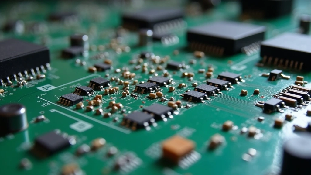
Ceramic capacitors appear in virtually every electronic device manufactured today. Their versatility stems from diverse capacitance values, voltage ratings, and temperature characteristics available across different manufacturing variants.
Power Delivery Networks: In modern processors and high-performance chips, ceramic capacitors form critical power delivery networks (PDNs) that supply stable voltage to silicon cores. These capacitors must exhibit extremely low ESL and ESR to respond instantaneously to current demand spikes. Thousands of ceramic capacitors work in parallel to minimize impedance across frequency ranges from DC to gigahertz.
Signal Coupling and Decoupling: Ceramic capacitors decouple power supply noise from sensitive analog circuits, preventing signal degradation. They couple AC signals between amplifier stages while blocking DC components. Their frequency-dependent impedance makes them ideal for these applications.
Filtering and RF Applications: High-frequency circuits employ ceramic capacitors in RF filters, matching networks, and impedance transformation circuits. Their low ESL enables operation at frequencies reaching gigahertz ranges, essential for wireless communications and radar systems.
Timing and Oscillator Circuits: Class I C0G capacitors provide the stability required for precision oscillators and timing circuits. Their minimal temperature and voltage coefficients ensure consistent frequency performance across environmental variations.
Energy Storage: Supercapacitor-like ceramic variants bridge the gap between conventional capacitors and supercapacitors, storing significant energy for backup power applications, flash photography circuits, and energy harvesting systems.
When exploring the broader technology landscape, understanding how artificial intelligence impacts electronics design reveals how AI algorithms now optimize capacitor placement and selection in complex circuit boards.
Selection Guide and Best Practices
Choosing appropriate ceramic capacitors requires careful consideration of multiple factors:
Capacitance Value and Tolerance: Calculate required capacitance based on circuit function (filtering, coupling, timing). Select tolerance grades matching application precision requirements. Cost-sensitive designs accept ±20% tolerance, while precision circuits demand ±5%.
Voltage Rating and Derating: Choose voltage ratings exceeding peak voltages in your circuit by at least 20%, preferably 50%. Apply 80% derating factors to extend component lifespan and ensure reliability. Never operate capacitors at rated voltage limits in production designs.
Temperature Considerations: Evaluate operating temperature ranges and select appropriate dielectric classes. Class I C0G capacitors suit precision applications across wide temperatures. Class II X7R variants suffice for most general-purpose needs. Avoid Y5V and Z5U unless applications tolerate significant capacitance variations.
Frequency Response Requirements: For high-frequency applications, prioritize low ESL designs. Minimize lead lengths and employ proper PCB layout techniques. Consider multiple smaller capacitors in parallel rather than single large units to reduce impedance.
Reliability and Qualification: Specify automotive-grade components (AEC-Q200) for vehicle applications. Military-grade variants (MIL-PRF-39014) suit defense and aerospace systems. Commercial-grade capacitors suffice for consumer electronics. Review manufacturer reliability data and failure rate statistics.
Cost Optimization: Ceramic capacitors offer excellent cost performance. Bulk purchasing reduces per-unit costs dramatically. Design for standard package sizes (0402, 0603, 0805) available from multiple suppliers to ensure competitive pricing and supply chain flexibility.
For those building custom systems, reviewing data recovery techniques reminds us that even electronics professionals must understand system reliability across all components.
Common Issues and Troubleshooting
Despite their reliability, ceramic capacitors can exhibit issues when improperly selected, derated, or installed:
Capacitance Aging: Some Class II ceramics experience gradual capacitance reduction over time, particularly when operated at elevated temperatures. This aging effect, typically 2-5% per decade, occurs due to domain relaxation in ferroelectric materials. Selecting appropriate derating and temperature classes mitigates this concern.
Voltage Coefficient Effects: Class II capacitors exhibit voltage-dependent capacitance, with values decreasing as applied voltage increases. This effect can significantly impact circuit performance in circuits with high voltage variations. Class I C0G capacitors eliminate this issue but at reduced capacitance density.
Mechanical Stress and Cracking: Thermal cycling and mechanical vibration can stress multilayer ceramic capacitors, potentially causing internal cracks. Proper PCB design, thermal management, and vibration isolation prevent these failures. Avoiding excessive solder reflow temperatures protects components during manufacturing.
Resonance Issues: Ceramic capacitors exhibit impedance resonance peaks at specific frequencies determined by ESL and ESR. These resonances can cause unexpected circuit behavior or instability. Using multiple capacitors with different values in parallel spreads resonance peaks across broader frequency ranges.
DC Bias Effects: Applying DC voltage to Class II capacitors reduces their effective capacitance significantly. Datasheets typically provide DC bias curves showing capacitance reduction at various voltage levels. Design circuits accounting for these reductions to maintain performance.
Understanding broader technology trends, including cloud computing infrastructure, shows how massive data centers depend on millions of ceramic capacitors maintaining stable power delivery to servers processing information worldwide.
FAQ
What is the difference between X7R and Y5V ceramic capacitors?
X7R capacitors maintain ±15% capacitance variation across -55°C to +125°C temperature ranges with ±15% voltage coefficient, suitable for general-purpose applications requiring moderate stability. Y5V variants accept ±82% variation across -30°C to +85°C with ±82% voltage coefficient, offering higher capacitance density but limited stability. X7R suits most production designs, while Y5V appears only in cost-critical applications tolerating wide parameter variations.
How do multilayer ceramic capacitors achieve such high capacitance in small packages?
Multilayer ceramic capacitors stack dozens or hundreds of thin ceramic dielectric layers alternating with metal electrodes. This parallel arrangement dramatically increases effective plate area within minimal volume. A 0402-sized MLCC might contain 200+ layers, achieving capacitance values approaching microfarads despite diminutive dimensions. Modern manufacturing techniques enable layer thicknesses approaching single micrometers.
Why do ceramic capacitors fail in power delivery networks?
Ceramic capacitors can fail in PDNs when subjected to excessive voltage spikes, thermal cycling stress, or mechanical vibration during high-current transients. Proper derating (operating at 50-80% rated voltage), thermal management, and mechanical mounting techniques prevent these failures. Using multiple smaller capacitors distributed across PCBs improves reliability compared to concentrated high-value units.
Can ceramic capacitors replace electrolytic capacitors directly?
Ceramic capacitors cannot universally replace electrolytics due to capacitance density limitations and cost considerations. Achieving equivalent microfarad values requires numerous ceramic units. However, for high-frequency applications and non-polarized requirements, ceramics are superior. Hybrid designs often combine small electrolytic capacitors for bulk storage with numerous ceramic units for high-frequency filtering.
What does the C0G designation mean?
C0G (Class I) designation indicates a ceramic capacitor with C temperature coefficient (±30 ppm/°C) and G capacitance change (±2% from -55°C to +125°C). The designation ensures minimal capacitance variation across temperature ranges, essential for precision circuits. NP0 represents the same specification using alternative naming conventions. These capacitors exhibit excellent stability but lower capacitance density than Class II alternatives.
How important is ESL in ceramic capacitor selection?
ESL (Equivalent Series Inductance) becomes critically important at frequencies above 10 MHz. Low ESL enables capacitors to respond instantaneously to current transients, essential in power delivery networks for modern processors operating at gigahertz frequencies. Minimizing PCB trace lengths and employing proper layout techniques reduce effective ESL. For low-frequency applications, ESL importance diminishes significantly.
For additional technology insights, explore our comprehensive technology blog covering emerging gadgets and electronics innovations shaping the future.
Understanding ceramic capacitor technology empowers electronics enthusiasts and professionals to design more reliable, efficient circuits. Whether you’re optimizing laptop power delivery systems or developing specialized industrial equipment, ceramic capacitors remain indispensable components deserving deep technical knowledge.